
DC Electromagnetic Brakes DBM Series – Adjustment, Drawing & Operation
DMB Electromagnetic brakes are actuated by energy stored in the compression spring and are released by a dc electromagnet.
Thus, the brake is fail-to-safety and is normally ON (applied). The dc magnet coil. when energized releases the brake.
This series of brakes are characterized by robust construction and design and is especially suited for Steel Mills, Hoists, EOT Cranes and Elevators,
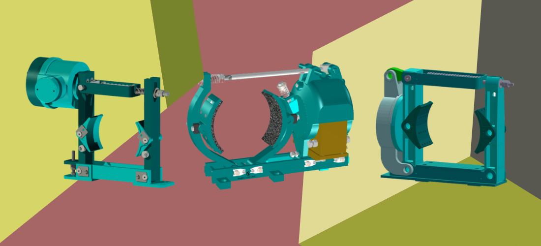
Construction of DC Electromagnetic Brakes
A pair of brake shoes, with bolted brake liners, are hinged in a v-shaped groove in cast steel arms. A strong dc electromagnet is encased in a steel enclosure and is bolted on the base frame. The two moving parts of the magnet are hinged on the base frame. These are held apart by an air gap and are stressed by a strong compression spring-loaded by a torque adjusting nut when the brake coil is not energized. The sidearm is pulled by the magnet body by a tie-rod.
The other half of the magnet body pushes the main arm on the brake drum. The lower ends of the shoes are pressed against each other in a ball-and-vee shape arrangement for synchronizing their movement.
Operation
When the magnet coil is not energized, the brake liners are pressed on the brake drum due to the push-pull force exerted by the compression spring. When the coil is energized by a (220V) de source, the two magnet bodies are attracted to each other. This results in.
(1) Closing the air gap to zero.
(2) Pushing the sidearm away from the brake drum,
(3) Releasing the pressure on the sidearm and releasing the brake, brake drum.
(4) Compressing the spring and storing energy for the next braking cycle.
This releases the brake.
When the dc source is cut off by switching off intentionally or by power failure, the magnet is demagnetized, the energy stored in the coil spring is released, and the two magnet body parts move away from each other, the two arms close the brake shoes on the drum and the brake is applied.
Features
Robust construction and simple design.
2.Reliable and consistent braking torque.
3.Efficient distribution of forces
4. Brake shoe replacement is easy and without dismantling
5.Ease of torque adjustment.
Selection of Braking Torque
The braking torque is generally decided as a percentage of rated torque of the drive motor.
Rated torque of the motor is given by
T=716.2 x (HP/RPM) kg-m
OR
M=0.974 x (KW/RPM) N-m
As guidance, the required braking torque, as a proportion to the motor rated torque Mb for the type of application is given by
Hoisting/Lifting Application 180% to 300%
CT/LT, Traveling Drives 80% to 180%
Retarding of high inertial drives like centrifuge 50% to 150%
Machine Tools 100% to 250%
Stopping Time Estimations
Average time “tb” (sec) required to stop moving inertia “J” (kg-m sq)
From initial speed “n” (rpm) under effective braking torque from all causes, “M” (N-m) is calculated as Tb=Jxn/(Mx9.55)……..seconds
If the load of mass “m” (kg) is moving with a linear speed “v” (m/sec) is to be referred to motor shaft “Jm” is given by JM=91.2xmx(v/n)²
Specifications
Class of insulation of coil Class “F”
Maximum coil voltage 600 V
Operation per hour 20 million cycles
Resistors wire wound
AC Side Interruption
The brake can be applied by cutting off the supply be for rectification (AC cut off) or after rectification (DC cut off)
Brake cut off on the AC side gives delayed stopping time.
Braking time in both cases is the same.
Total stopping time tB + tA.
Where tA is brake application delay.
Know what DC Electromagnetic Brake – DM Series is?
Rectifier Control Panel for D.C Barkes