
Thruster Brake – Working Principle, Construction & Operation
Everything You Keen To Know About Mill Duty Thruster Brake
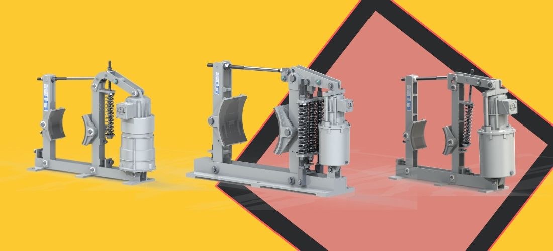
Thruster brake is a device to retard the speed of moving machinery and to stop it accurately to the desired position. The braking force is applied to the brake shoes by a prestressed compression spring
The shoes press on the train brake drum retarding its speed, and finally stop it The releasing of the brake and compressing of the spring is done by thruster Other release devices like a pneumatic cylinder or manual release arrangements can be offered on request.
Know-How Mill Duty Thruster Brake is Built.
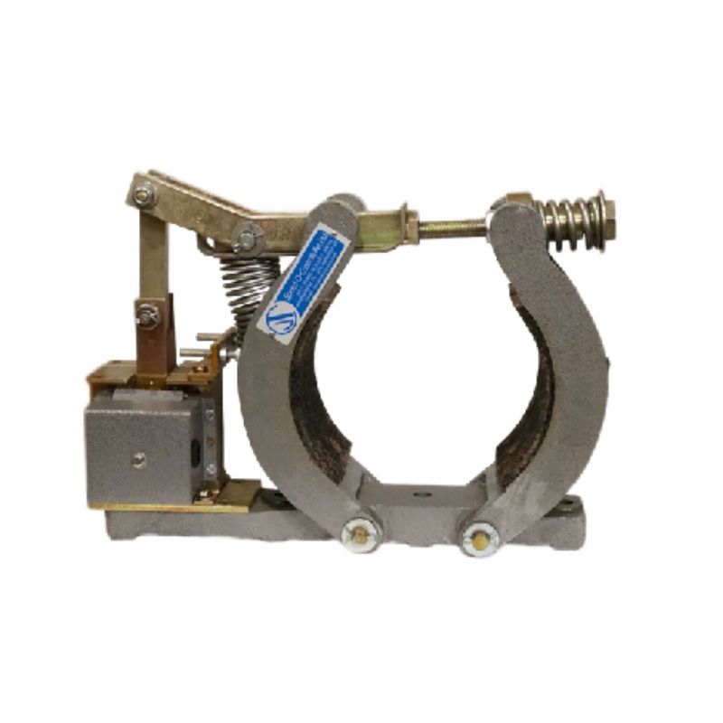
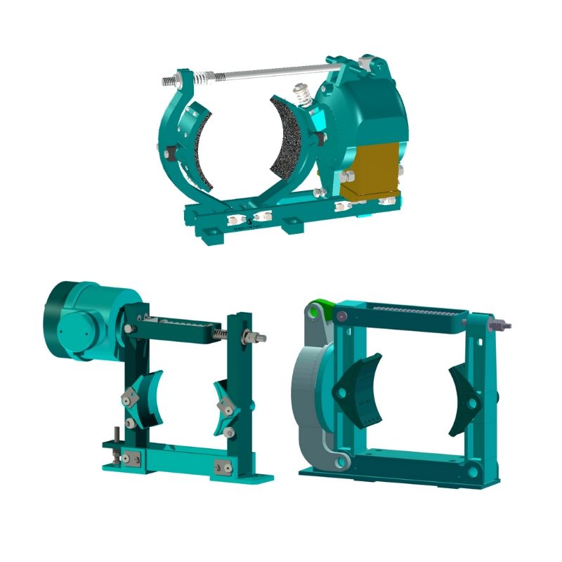
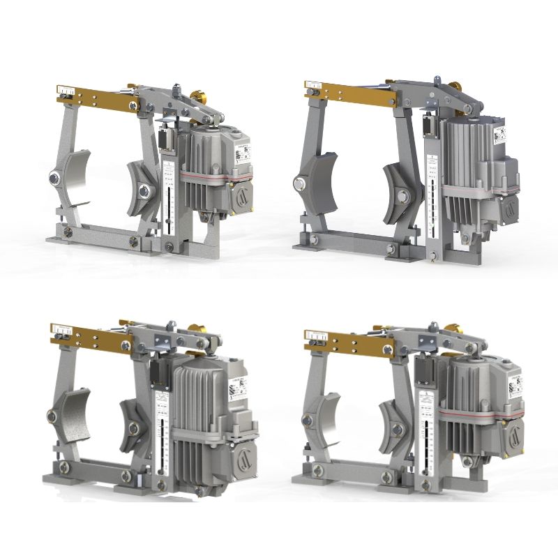
A thruster shoe brake has a pair of cast iron shoes that are lined up with friction pads. The shoes are hinged on the main arm and sidearm of the brake, each of them has a hinge pin fitted in the base. They are connected to each other on top by a tie rod, which is hinged in the main arm and locked to the swivel block in the sidearm, by a lock nut.
A crank lever is hinged on the main arm, and the other end is fixed to the top clevis of the thruster by a hinge pin. A brake spring is fixed on the main arm and is pre-loaded by a lock nut on the lever The pre-tension in this spring decides the braking torque. The thruster is fitted on the base by a hinge pin.
How It Works.
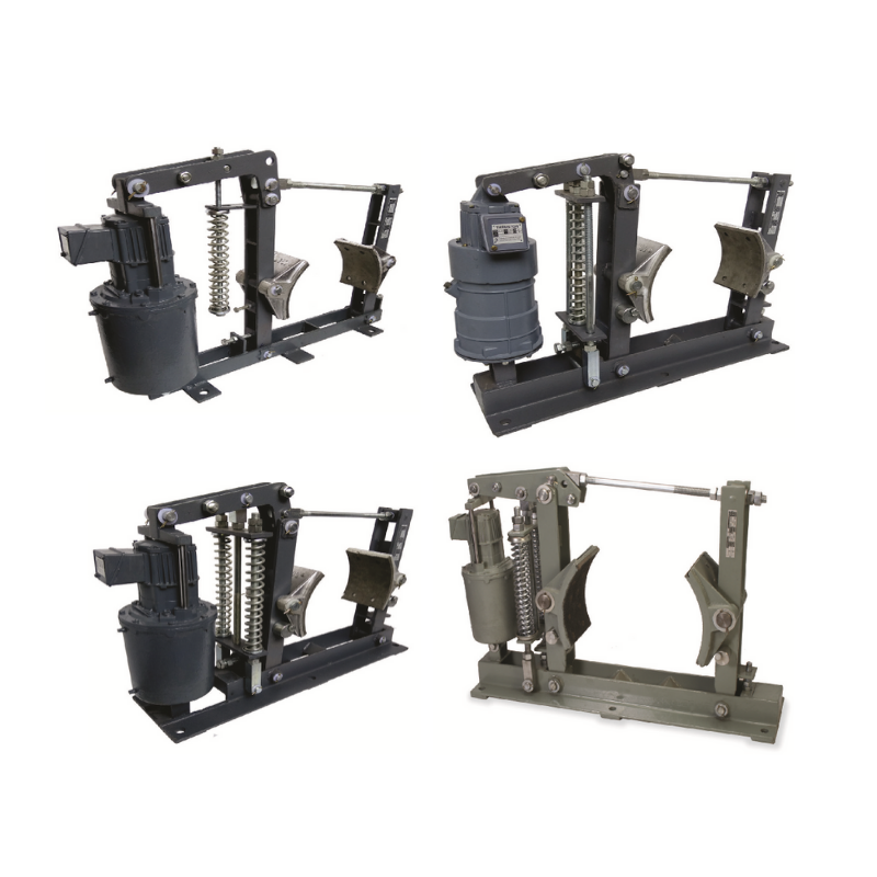
When the thruster is not energized, the brake shoes are pressed on the brake drum fitted on the drive motor shaft and hold it under the effect of braking force provided by the spring. In such a condition, the brake is applied, and the drum cannot rotate.
But when the thruster motor is energized, the thrust provided by the thruster lifts up the crank lever which moves the arms, and the shoe brakes away from the brake drum and releasing the braking force. The spring is compressed and braking energy is stored for the next cycle.
How to Proceed With the Foundation to Install the MDT Thruster Brake
To install the Brake, the foundation must be made ready with tapped holes of the proper size of tapped holes as per the dimensions mentioned in the dimension table. Care must be taken to ensure the centerline of the brake coincides with the centerline of the brake drum aligned and also the level of mounting pads “h” is matching with the center height of the brake drum.
How to Install Brake in the Position
To Insert the Brake in position the brake shoe is to be taken apart to clear drum diameter. To do this, slacken the setting bolts and the tie-rod nuts in the sidearm and pull it slightly. This will increase the distance between the brake shoe and the brake can now be inserted on the foundation bolts and the shoes can be positioned on the brake drum. Retighten the setting bolt and the tie-rod nuts. Tighten the mounting bolts.
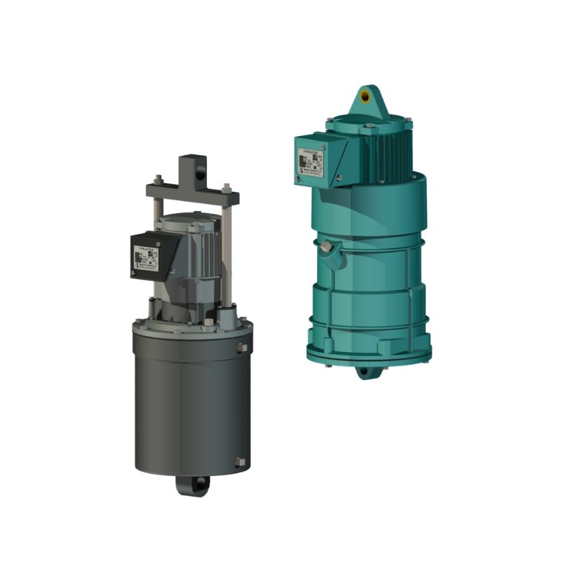
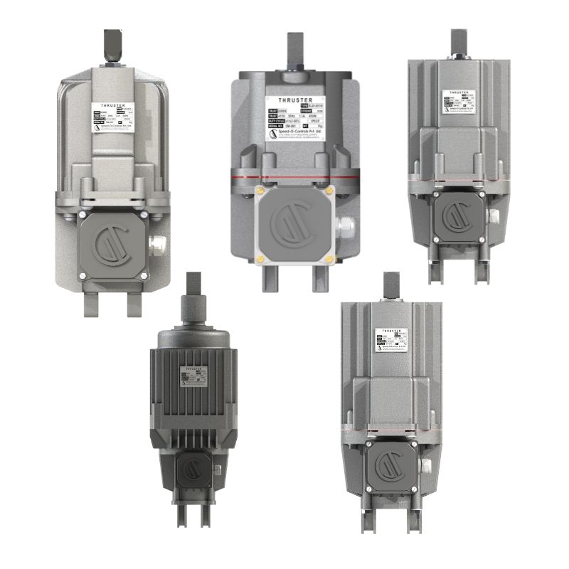
How to properly Install Thruster on Brake
The thruster is to be filled with a sufficient quantity of oil as mentioned in the Thruster Table. To mount the thruster on the brake, remove one side split pins on the thruster hinge pins of the brake and the lever. Remove both pins and re-insert them after positioning the thruster on the pinholes in the base and lever of the brake, Replace both split pins. Check that the thruster movement is unobstructed when the crank lever is pulled manually and the thrust rod of the thruster moves freely.
Open the terminal box cover of the thruster and connect 3-phase, 415 Volt power supply cables to the three terminals on the terminal plate inside the terminal box. Terminate the earthing lead on the earth terminal provided on the thruster or brake. Replace the terminal box cover on the terminal box. The thruster is ready for operation.
How to Do Aligning and Setting of Brake
Next, align the brake shoes with the diameter and surface of the brake drum and adjust the nuts on the tie-rod such that both shoes grip the brake drum equally. Energize the power cables, this will cause the thrust rod of the thruster to move up and the brake is released as the shoes release the brake drum. Adjust the gap between the drum and shoes to 0.3 to 0.5 mm equally by adjusting the setting bolts on both arms.
For equal and uniform linear wear it is necessary to ensure that the shoes and the arms move equally. This done automatically by the ball on one arm and a matching vee on the other arm.
Know-How to perfectly set the brake shoe
The Shoe setting screws to be adjusted when the brake is released. Both shoes must have an equal gap between the drum and the linear. Also, the top and bottom corners of the liners are to be equal distance from the drum surface. The setting can be done with the feeler gauge. The recommended gap between the liners and the drum is between 0.3 to 0.5mm. Ensure that the brake drum is free to rotate when the brake is released.
Know the significant barking torque required
The Braking torque “ Ma” (n-m) required to stop the rotating masses of the total moment of inertia “J” (kg-msq), from the speed of “n” (rpm) in time “t” (s) is given by Mʙ=j 𝘅 n / (9.55 𝘅 t) newton-meters.
Know-How to Adjust the Braking Torque
To adjust the braking torque to the desired value, the preloading of the compression spring is to be done by top nuts up the spring tie rod. To increase torque, turn nuts clockwise. The adjustment of the braking torque is very critical. High braking torque results in a rapid stoppage. For most applications, braking torque of about 150 to 250% of rated torque of the drive motor is sufficient.
To Buy Mill Duty Thruster Brake Click Now
To See Other Brakes Click Now
Technical Data
|
Brake Model
|
Brake Drum Dia mm
|
Brake Torque | Thruster Details |
C
|
N
|
P
|
Q
|
Mass Kg
|
||||
| Kg-m | N-m | Model | Force kg | Force (N) | Stoke (S) | |||||||
| MDT-100-18 | 100 | 6 | 60 |
ST 520
|
18
|
180
|
51
|
159
|
349
|
110
|
90
|
17 |
| MDT-150-18 | 150 | 9 | 90 | 20 | ||||||||
| MDT-160-18 | 160 | 9 | 90 | 20 | ||||||||
| MDT-200-18 | 200 | 20 | 200 | 27 | ||||||||
| MDT-250-18 | 250 | 35 | 350 | 30 | ||||||||
| MDT-300-18 | 300 | 42 | 420 | 35 | ||||||||
| MDT-200-34 | 200 | 32 | 320 |
ST 535
|
34
|
340
|
51
|
171
|
444
|
138
|
110
|
27 |
| MDT-250-34 | 250 | 42 | 420 | 30 | ||||||||
| MDT-300-34 | 300 | 32 | 320 | 70 | ||||||||
| MDT-400-34 |
400
|
90 | 900 | 85 | ||||||||
| MDT-400-46 | 110 | 1100 | ST 545 | 46 | 460 | 85 | ||||||
| MDT-400-68 | 170 | 1700 | ST 870 | 68 | 680 | 76 | 215 | 508 | 152 | 124 | 88 | |
| MDT-500-46 |
500
|
190 | 1900 | ST 545 | 46 | 460 | 51 | 171 | 444 | 138 | 110 | 125 |
| MDT-500-68 | 290 | 2900 | ST 870 | 68 | 680 |
76
|
215
|
508
|
152
|
124
|
125 | |
| MDT-500-114 | 485 | 4850 | ST 8110 | 114 | 1140 | 125 | ||||||
| MDT-600-68 |
600
|
350 | 3500 | ST 870 | 68 | 680 | 190 | |||||
| MDT-600-114 | 580 | 5800 | ST 8110 | 114 | 1140 | 190 | ||||||