
Electro Hydraulic Thruster ST Series Operation, Installation & Specifications
Electro-Hydraulic Thruster ST is a device which develops linear thrust (or force) required to operate the required mechanism. The input to the device is Three phase supply. The thrusters are widely used to actuate Thruster Shoe Brakes, commonly used in material handling machines. Thrusters in various models develop 100 N (10 kg f) to 3000 N (295 kg f) Force.
Features of Electro-Hydraulic Thruster ST
- The thruster provides a non-jerking, linear thrust of constant magnitude throughout is and working stroke
- The thruster does not need any external tool components or accessories for operation
- Compact and rugged construction and long maintenance-free service
- Low power consumption and low heat generation
- High number – up to 720- of starts per hour.
- The motor is totally enclosed non-ventilated and together with the terminal box provides IP44 degree of protection IP-55 degree of protection can be provided against specific requests.
Principle of Operation
On supplying electrical power to the motor the impeller mounted on the motor shah rotates. The impeller draws oil from the low- pressure area and discharges it in the high-pressure chamber This increased pressure moves the piston to produce thrust The piston is arrested by a stopper shoulder at the end of the stroke and remains in that position delivering the full thrust till the electrical power is on.
When power is switched off the building up of pressure stops. The external load (usually the spring force of the thruster brake) forces the piston down, and the oil is flushed out of the cylinder. A built-in ac induction motor drives the impeller. The radial impeller blades enable operation in both directions of rotation of the impeller supply cable can be terminated in any R-Y-B phase sequence. The motor windings are the star (wye) connected, with an internal star point.
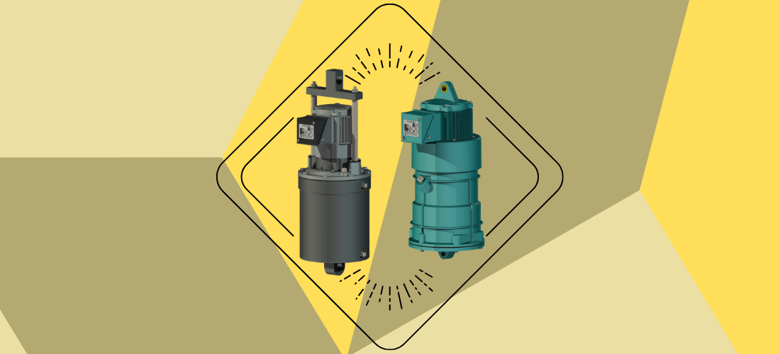
Thruster: ST-515/ST-520
A compact, a built-in ac induction motor is directly mounted on the top of a moving aluminum piston. A cast-iron tank containing the brake fluid acts as the cylinder. The piston separates the cylinder into high pressure and low-pressure chambers. The impeller is keyed on to the motor shaft. The thruster is mounted on upper and lower clevis,
Thruster: ST-535… ST-13300
Thrusters of this type have two thrust rods mounted on the moving piston and the top eleven is a plate connecting them. The close-ended oil tank with bottom clevis holds oil and also acts as the cylinder. The built-in motor is housed in the top cover. The bi-directional radial vane impeller is mounted on the motor shaft. The moving piston separates the high and low-pressure compartments in the oil tank. The spacer bushes control the stroke of the thruster.
The output capacity of the motor, the diameters of the pistons, and the sizes of the impellers decide the output thrust of the thrusters. Various models of this type of thrusters deliver thrust ranging from 340 N (34 kg 1) to 2350 N (235 kg f)
Electrical Supply
Unless otherwise specified, all thrusters are suitable for operation for 415 Volts, 3-phase, 50 Hz power supply. Thrusters for other voltages up to 600 v ac, 3-phase can be supplied against specific inquiries.
Connections
The thrusters operate equally well in both directions of rotation. Therefore, the three-phase supply lines can be connected to the thruster in any R-Y-B phase sequence. Provide adequate electrical safety backups.
Oil Requirments
Thrusters are supplied without oil to avoid spillage during transportation. They must be filled with a sufficient quantity of oil before installation. For all models of thrusters, it is recommended to use Transformer Oil as specified in BS:148.
Oil capacity requirements are listed in the table
Know- Installation of Electro-Hydraulic Thruster ST
All thrusters are suitable for vertical mounting only. After filling the thruster with the required quantity of oil, install it by using the clevis and hinge pins provided. Insert the locking split pins. Ensure that no excessive transverse forces are acting on the thrust rod. Wipe out the dust, dirt, paint, or oil deposits from the operating section of the thrust rod/pins by a dry and clean cloth.
Know- Maintenance of Thruster
The thruster is designed for long trouble-free service. The motor windings are designed to meet contingencies. The bearings are adequately sized.
Routine maintenance schedule includes checking the oil levels and topping them if necessary. If oil contamination is detected, drain it out completely and refill with fresh oil. Check and correct the oil leakage is detected.
Click Here to Buy it, See for all Variations!